Module: Isosurface
Maps volumetric data creating surface of constant data values. Creates a series of isosurfaces from 3D data.
| input port | type | description | data acceptors |
|---|---|---|---|
| inField | VNField | Input for data field to extract isosurface | [Large] Regular Field 3D Irregular Field scalar componentwith 3D cells |
| output port | type | description | data schemas |
|---|---|---|---|
| isosurfaceField | VNIrregularField | Output for surface field | Irregular Field 0 cell setswith TRIANGLE cells |
| outObj | VNGeometryObject |
Description
The module creates a series of isosurfaces for 3D data.
Input data
At input the module requires a 3D data field.
Output data
At output there is an irregular surface field and a geometry object.
Computation tab
Preprocessing
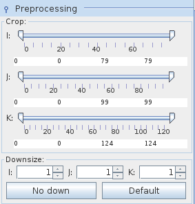
Preprocessing is available for regular data fields.
The Crop sliders select the geometric extents of the regular input field, i.e. lower and upper bound array indices in their respective dimensions.
The downsize factors can be adjusted using the Downsize spinners. It reduces the size of the field, saving processing time and memory by "thinning out" the data. Default downsize values depend on the size of the input field and are chosen automatically.
The No down button reverses downsize.The Default downsize button restores default downsize.
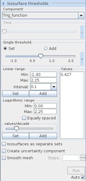
Isosurface thresholds
The threshold Component drop down list defines the component of the input field for which an isosurface will be generated. By default, the first component of the list is used. For vector fields its norm is calculated.
In the case of time dependent data the user can choose a time step or an interpolated time value between two time steps using the Time slider.
The Single threshold slider enables the user to choose an isosurface value using either the slider or the text input fields for minimum, maximum and current value on the right hand side of the slider. The text input fields appear with mouse click at + on the right hand side of the slider, and disappear with mouse click at -.
A radio button menu allows values to be set and added_._ If Set is switched on the slider determines a value for one isosurface. If Add is switched on, every further slider value defines an additional isosurface associated with the value. By default the set modus is switched on.
In the Linear range field the user can choose a set of evenly spaced isosurface values between the Min and Max value and a user defined Interval. Press the Set button in order to generate a new set of values, press the Add button in order to add new values.
Similarly, in the Logarithmic range field the user chooses isosurface values which are logarithmically spaced between Min and Max value.
The values/decade slider determines the number of isosurfaces per decade.
If the Equally spaced check box is switched on isosurfaces in each decade are equally spaced.
All values of generated isosurfaces are listed in the Values text field. In order to remove values from the list select the values and choose Remove selected from a context menu which appears with right mouse click. The Remove all_ _option removes all but one value from the list.
If Isosurfaces as separate sets check box is switched on every isosurface comes as a separate cell set at output. By default this option is switched off.
If the Create uncertainty component option is switched on the module generates a function which reflects uncertainty in isosurface generation. The name of this new variable is the name of the isosurface variable plus the ending uncertrainty. This variable also appears at output.
The Smooth mesh option allows one to smooth isosurfaces by a rate chosen on the right hand side of the Smooth mesh check box.
Each parameter change is processed dynamically if the Auto check box is switched on. If it is switched off processing is caused by pressing the Run button. The yellow button means that there are unprocessed parameter changes.
By default the Auto check box is switched on.
Presentation tab
Presentation tab contents are described in the common interfaces section unter the Presentation Panel entry.
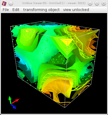
Example
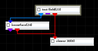
Choose the test field module from test objects library and isosurface module from 3D field mappers library and connect them.
In the test field module choose 3D. In the computation tab of the isosurface module choose_ Trig_function_ as threshold component.
In the linear range field choose min value -1.41, max value 2.26, interval value 0.2. Switch the isosurface as separate sets checkbox on. Press the set button in the linear range field.
In the presentation tab there appears a list of isosurface cell sets. Choosing a set the user can change its properties. Each cell set can have its own different presentation.