Module: Regular Field Slice
Slices a 3D regular field by fixing one of the indices at selected level
| input port | type | description | data acceptors |
|---|---|---|---|
| inField | VNRegularField | [Large] Regular Field 3D |
| output port | type | description | data schemas |
|---|---|---|---|
| outField | VNRegularField | Regular Field 2D |
|
| outObj | VNGeometryObject | Output of geometry object for 3D rendered volume |
Description
The regular field slice module extracts a regular 2D slice from a 3D regular field.
Input data
The input field is 3D regular.
Output data
At output there is a regular 2D field with affine geometry and a geometry object of the field.
Computation parameters
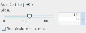
The Axis radio button panel defines the direction i, j, or k which is orthogonal to the slice plane.
The Slice slider picks the slice position. Default value is in the middle between minimum and maximum slice position. The user defines the slice value using either the slider or the text input fields for minimum, maximum and current value on the right hand side of the slider. The text input fields appear with mouse click at + on the right hand side of the slider, and disappear with mouse click at -.
If the Recalculate min, max option is switched on, the module recalculates min and max values for the chosen slice and the slice is colored according to these recalculated values. By default, this option is switched off, i.e. data are colored according to the global min and max values. This option does not influence the min and max value at output, which is the min and max for this slice.
Presentation parameters
Presentation tab contents are described in the common interfaces section unter the Presentation Panel entry.
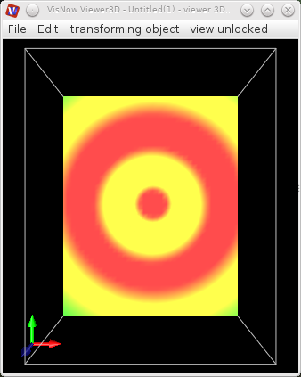
Example
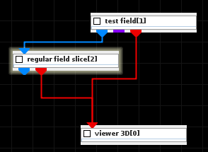
Choose a test field module from the test objects library, regular field slice module from the 3D field mappers library and connect them. In the test field module UI choose 3D, resolution=50 and Vortex.